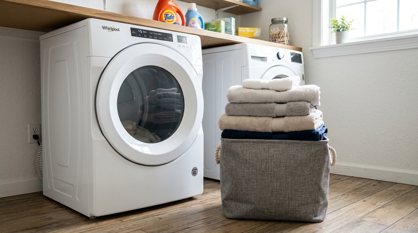
Whirlpool Clothes Dryer F3 Error Code: Step-by-Step Fix
Required Tools for this Fix
- Multimeter
- Screwdriver
- Replacement thermistor
Quick Summary Answer: The Whirlpool dryer F3 error code (often displayed alongside E1 or E2) indicates that the main control board detects an open or shorted exhaust thermistor circuit. The most common cause is a failed thermistor located on the blower housing, though loose wire harness connectors or a malfunctioning electronic control board can also trigger it. You can resolve the issue in most cases by unplugging the dryer, checking the thermistor’s electrical resistance with a multimeter (it should read roughly 10,000 ohms at room temperature), and replacing the sensor if it reads open or shorted.
What Does the Whirlpool Dryer F3 Error Code Mean?
When your Whirlpool clothes dryer throws an F3 code, the machine has locked out its cycle to protect internal components and clothing from uncontrolled temperatures. Modern dryers rely on a solid-state sensor called a thermistor rather than a simple mechanical thermostat to monitor exhaust air. The electronic control board sends a low-voltage DC signal through this thermistor to measure operating heat.
If the control board reads infinite resistance, zero resistance, or a voltage signal outside the calibrated operating range, it aborts the cycle and displays the F3 error. Without accurate temperature readings, the control board cannot regulate the gas valve or heating element safely.
Understanding the specific sub-code helps you pinpoint the exact electrical failure:
- F3 E1 (Exhaust Thermistor Open): The control board detects an open electrical loop (infinite resistance), indicating broken internal wiring inside the thermistor or an unplugged harness.
- F3 E2 (Exhaust Thermistor Shorted): The sensor’s internal resistance has collapsed to near-zero ohms, creating a short circuit that reads as extreme, instant overheating.
- F3 E3 (Inlet Thermistor Open): Found on select steam-assist or hybrid heat pump models, signaling a disconnected or broken inlet air channel sensor.
- F03 / F3 (Legacy Display): On older digital interfaces without alphanumeric sub-codes, this defaults directly to an exhaust thermistor circuit fault.
[Main Control Board] <--- (DC Low-Voltage Signal) ---> [Exhaust Thermistor]
         |                                                      |
    Checks Ohms                                           Varies Ohms
 (F3 = Circuit Broken)                                (Normal: ~10kΩ @ 77°F)
Diagnostic Quick Reference
We compiled this summary table to help you assess the tools, budget, and time commitment required to diagnose and repair the F3 fault code.
| Diagnostic Step | Est. Time | Tools Needed | Est. Cost (DIY) |
|---|---|---|---|
| System Hard Reset | 5 mins | None | $0 |
| Diagnostic Service Mode | 5 mins | None | $0 |
| Blower Housing Disassembly | 15 mins | 1/4” Nut Driver, Putty Knife | $0 |
| Wiring Harness Continuity Check | 10 mins | Multimeter, Work Gloves | $0 |
| Thermistor Resistance Bench Test | 10 mins | Digital Multimeter | $0 |
| Thermistor Replacement | 15 mins | 1/4” Nut Driver | $15 – $35 |
| Main Control Board Replacement | 25 mins | Screwdriver Set, Nut Drivers | $120 – $260 |
WARNING: ELECTRICAL SHOCK AND INJURY HAZARD
Always disconnect the dryer from electrical power before removing any service panels. For electric models, unplug the 240V cord or switch off both circuit breakers in your main electrical panel. For gas models, unplug the 120V power cord and turn the manual gas supply shut-off valve to the closed position. Working on energized appliances can cause severe electric shock, electrocution, or physical injury.
Required Tools and Replacement Parts
Gather your diagnostic equipment before taking the dryer apart. Having these items on hand ensures you can complete the repair in a single session:
- Digital Multimeter: Capable of reading direct resistance in ohms ($\Omega$) from the single-ohm range up to 50k $\Omega$.
- 1/4-inch Nut Driver: Standard size for Whirlpool sheet metal cabinet and blower housing screws.
- 5/16-inch Nut Driver: Used on select rear panel fasteners and motor mount brackets.
- Flathead Screwdriver or Stiff Putty Knife: For releasing top panel spring clips on front-load configurations.
- Phillips Screwdriver: Required for console removal on select models.
- OEM Replacement Thermistor: Part numbers vary by model (commonly WP8577274, WP3976615, or W10839828). Always verify your exact dryer model number on the door jamb sticker.
Step-by-Step Diagnostic and Testing Checklist
Follow this structured workflow to isolate the root cause without spending money on parts you do not need.
[Start Diagnosis]
       |
[Perform Hard Reset] ---> Fixed? ---> [Done]
       | (No)
[Run Diagnostic Test Mode]
       |
[Inspect Wiring & Terminals] ---> Loose/Burnt? ---> [Repair Harness]
       | (Intact)
[Multimeter Test Thermistor] ---> Out of Range? ---> [Replace Thermistor]
       | (Normal: ~10kΩ)
[Check Wire Continuity to Board] ---> Open Line? ---> [Replace Wiring]
       | (Passes)
[Replace Electronic Control Board]
1. Perform a Hard Power Reset
Modern control boards can occasionally lock up due to electrical line noise or power surges.
Unplug the dryer power cord from the wall outlet completely. Leave the unit disconnected for at least 10 full minutes to allow the control board’s internal capacitors to discharge.
Plug the power cord back in and attempt to run a short “Timed Dry” cycle on Medium heat. If the F3 code returns immediately or within two minutes, the hardware circuit is physically broken.
2. Enter Diagnostic Service Mode
Entering diagnostic mode allows you to check stored error codes and view real-time thermistor readings directly on the console display.
- Ensure the dryer is in Standby mode (plugged in, but all indicator lights off).
- Select any button on the console (except Power, Cancel, or Start). We suggest using the Dryness Level or Temp button.
- Press and release the selected button in this exact pattern: Press, Release, Press, Release, Press, Release. Keep intervals between presses under 1 second.
- If successful, all console LEDs will illuminate, and the display will flash
88or enter diagnostic mode. - Note any stored fault codes that cycle on the digital screen.
If the screen reads F3 E1 or F3 E2, the board confirms that the exhaust thermistor circuit failed during active operation. Exit service mode by pressing the Cancel or Power button once.
Component Access and Location
The exhaust thermistor sits directly on the blower wheel housing to sample the temperature of air leaving the drum. Depending on your Whirlpool chassis, access requires opening either the front lower panel or the rear sheet metal panel.
           +---------------------------------------+
           |             Whirlpool Dryer           |
           |                                       |
           |             [ Drum Area ]             |
           |                                       |
           +---------------------------------------+
           |  [Blower Fan]        [Exhaust Duct]   |
           |        \                  /           |
           |      [ EXHAUST THERMISTOR ]           |
           |      (Mounted on Blower Cover)        |
           +---------------------------------------+
Front-Access Models (Cabrio / Older Duet with Lower Access Panel)
- Remove the screws securing the small toe panel below the main dryer door.
- Pull the bottom panel forward and down to disengage the top retaining tabs.
- Locate the white plastic blower housing on the left or center-left side.
- The thermistor is the small, oval or rectangular plastic component held in place by two 1/4” hex screws, fitted with two thin blue or white wires.
Rear-Access Models (Alpha Platform / Modern Front-Loaders)
- Pull the dryer away from the wall to reach the back panel.
- Disconnect the metal vent exhaust duct.
- Remove the perimeter 1/4-inch sheet metal screws securing the large rear panel.
- Set the panel aside to expose the drive belt, motor, and blower housing.
- Locate the thermistor mounted adjacent to the blower wheel exhaust chute.
Testing the Thermistor With a Multimeter
The thermistor is a Negative Temperature Coefficient (NTC) resistor. As its temperature increases, its electrical resistance decreases. Testing it requires checking both room-temperature resistance and response to heat.
                +-----------------------------+
                |    DIGITAL MULTIMETER       |
                |          [ 10.05 kΩ ]       |
                +-----------------------------+
                     | (-)               | (+)
                     v                   v
                [Terminal A]        [Terminal B]
             +-----------------------------------+
             |       EXHAUST THERMISTOR          |
             |       (Plastic Housing)           |
             +-----------------------------------+
Step 1: Disconnect the Wiring
Never test the thermistor while the dryer’s wiring harness remains connected. You will read back-feed resistance from the control board, which invalidates your measurements. Gently pull the two slip-on wire connectors off the thermistor tabs using needle-nose pliers or your fingers.
Step 2: Set Up the Multimeter
Turn your multimeter dial to the Resistance ($\Omega$) setting. If your meter is manual-ranging, select the 20k $\Omega$ or 40k $\Omega$ scale.
Step 3: Take the Base Measurement
Touch the black and red multimeter probes firmly to the two exposed flat metal terminals on the thermistor.
- Normal Reading: At standard room temperature (68°F to 77°F / 20°C to 25°C), the multimeter should read between 9,500 and 10,500 ohms (9.5k $\Omega$ to 10.5k $\Omega$).
- Open Circuit (Failed): The multimeter displays
O.L.(Open Loop) or infinite resistance. This matches an F3 E1 error. - Shorted Circuit (Failed): The meter reads
0.00 $\Omega$or close to single-digit ohms. This triggers an F3 E2 error.
Thermistor Resistance vs. Temperature Chart
Use this reference table to evaluate your sensor at varying ambient temperatures:
| Sensor Temperature (°F) | Sensor Temperature (°C) | Expected Resistance Range |
|---|---|---|
| 50°F | 10°C | 18.0k – 21.0k $\Omega$ |
| 60°F | 15.6°C | 14.5k – 16.5k $\Omega$ |
| 70°F | 21.1°C | 11.0k – 12.5k $\Omega$ |
| 77°F (Standard Room Temp) | 25°C | 9.5k – 10.5k $\Omega$ |
| 85°F | 29.4°C | 8.0k – 9.0k $\Omega$ |
| 100°F | 37.8°C | 5.5k – 6.5k $\Omega$ |
| 140°F (Operating Heat) | 60°C | 2.2k – 2.8k $\Omega$ |
Step 4: Perform the Dynamic Heat Test
If the sensor passes the static room-temperature test, test its response to heat. Keep your multimeter leads connected to the terminals while holding the sensor body in your closed fist or blowing warm air over it with a hair dryer.
You should observe the resistance number steadily drop on your multimeter screen. If the reading jumps wildly, drops to zero, or shows breaks in resistance, the thermistor has degraded internally and requires replacement.
Checking the Wiring Harness and Main Control Board
If your thermistor measures within normal limits, the electrical interruption sits elsewhere in the circuit path.
[Control Board Connector P14] ========================== [Thermistor Terminals]
  (Pin 1 to Pin 2)                    Wiring Run             (Inspect for Cuts)
Inspect the Wiring Harness
Examine the two wires that run from the thermistor up to the main control board. Check for:
- Pinched wires against sharp edges of the sheet metal cabinet.
- Melted insulation caused by contact with the heating element housing or gas burner tube.
- Corroded, loose, or oxidized terminal spade lugs at the sensor plug.
Test Harness Continuity
- Locate the main control board (mounted inside the top console or behind the upper top panel).
- Find the machine control harness connector labeled for the thermistor (typically marked P14, P4, or TH2 depending on your schematic).
- Unplug this multi-pin harness connector from the control board.
- Measure resistance across the two designated thermistor harness pins while the sensor remains plugged in at the blower.
- If the reading matches your earlier measurement (~10k $\Omega$), the wiring is intact.
- If the reading shows
O.L., one of the harness wires has a physical break between the control board and the blower housing.
Diagnosing the Electronic Control Board
When both the thermistor and the wiring harness pass continuity and resistance checks, the sensor input channel on the main control board has failed. A failed micro-resistor or solder trace on the board will misread incoming sensor signals as an open loop. In this scenario, you must replace the main electronic control assembly.
How to Replace a Failed Whirlpool Dryer Thermistor
Replacing the exhaust thermistor is a simple, low-cost DIY repair. Follow these steps once you have confirmed the component has failed:
- Disconnect all power to the appliance.
- Access the blower housing through the lower front toe kick panel or the rear service panel.
- Unplug the two wire connectors from the thermistor spade terminals.
- Remove the mounting screws: Use a 1/4-inch nut driver to remove the one or two hex-head screws securing the sensor to the blower chute.
- Extract the old thermistor: Pull the plastic housing straight out. Inspect the mounting hole for excessive lint accumulation and clean it out.
- Mount the replacement sensor: Position the new OEM thermistor flush against the blower housing. Drive the 1/4-inch screws in by hand until snug. Do not overtighten, or you may crack the plastic mounting flange.
- Reattach the wiring: Push the two wire spade terminals firmly onto the new sensor tabs. Because the thermistor is a non-polarized resistor, either wire can connect to either terminal.
- Reassemble the cabinet panels: Reinstall the front or rear panels and ensure all ground wires and sheet metal screws are secured.
- Restore power: Plug the dryer back in and run a test cycle.
Thermistor vs. Thermal Fuse vs. High-Limit Thermostat
Homeowners frequently confuse the thermistor with other safety devices mounted nearby on the blower housing and heater duct. Each serves a distinct purpose:
+---------------------+-----------------------+-----------------------+
| Component           | Primary Function      | Multimeter Reading    |
+---------------------+-----------------------+-----------------------+
| Exhaust Thermistor  | Reads Variable Heat   | ~10k Ω (Varies)       |
| Thermal Fuse        | One-Time Safety Cutoff| 0.00 Ω (Closed Circuit)|
| High-Limit Cutoff   | Resettable Heat Switch| 0.00 Ω (Closed Circuit)|
+---------------------+-----------------------+-----------------------+
- Exhaust Thermistor: A variable resistor sending temperature data back to the board. It never cuts circuit power directly. If it fails, the dryer generates an F3 or related error code.
- Thermal Fuse: A non-resettable single-use safety switch. When blower temperatures exceed roughly 196°F, it blows open permanently. A blown thermal fuse prevents electric dryers from running or gas dryers from firing, but rarely displays an F3 code.
- High-Limit Thermostat: A mechanical bi-metal switch attached directly to the heating element box. It opens when airflow is completely blocked to prevent fires, then closes automatically once it cools.
Preventative Maintenance to Stop F3 Code Recurrence
An exhaust thermistor rarely fails due to age alone. Excessive internal cabinet heat and moisture back-pressure are the primary culprits behind premature sensor failure. Implement these maintenance habits to protect the replacement component:
1. Clean the Dryer Lint Trap Assembly
Clean the mesh lint screen before every load. Periodically remove the screen, vacuum deep down into the lint chute using a crevice tool, and wash the screen in warm soapy water to remove invisible wax films left by dryer sheets.
2. Clear the Exterior Vent Exhaust Duct
A crushed, kinked, or clogged 4-inch exhaust pipe traps hot, humid air inside the blower housing. This heat build-up causes extreme thermal swings that degrade the thermistor’s internal ceramic elements. We advise cleaning the complete length of your exhaust duct to the exterior wall cap once every 12 months using a rotary duct brush.
3. Replace Flexible Plastic Venting
Never use thin foil-plastic or ribbed vinyl accordion transition ducts. These trap lint within their ridges and collapse easily, causing massive airflow restriction. Replace them with semi-rigid or rigid aluminum ducting.
Frequently Asked Questions
1. Can I bypass the Whirlpool dryer thermistor to finish a load of laundry?
No, you must never bypass the exhaust thermistor. Unlike a standard mechanical thermostat, the thermistor communicates with the electronic microprocessor using precise resistance values. Jumping the thermistor terminals with a wire creates a dead short circuit ($0,\Omega$), which causes the control board to immediately throw code F3 E2 and shut down the dryer.
2. How much does it cost to fix an F3 error code professionally vs. DIY?
An OEM replacement Whirlpool thermistor costs between $15 and $35. Completing this repair yourself costs only the price of the part. Hiring a professional appliance repair technician typically costs between $150 and $250, which covers the diagnostic service fee, labor, and component markup.
3. What happens if I keep running the dryer when the F3 code is intermittent?
An intermittent F3 error means the thermistor has developed internal micro-fractures or has a loose connection. Ignoring this problem will result in uneven drying, extended cycle times, scorched clothing from overheated air, or eventual full shutdown when the component fails completely.
4. Why did my dryer show F3 right after I replaced the heating element?
If the F3 code appears immediately after replacing a heating element, you likely dislodged a wire on the nearby thermistor or cross-connected the wire harness during reassembly. Re-open the cabinet and ensure the two blue or white thermistor harness wires are securely connected to their designated terminal tabs.
5. How do I clear the F3 error code from the dryer’s memory after fixing it?
To clear the code after completing your repair, initiate the Diagnostic Service Mode (press any button three times in sequence, with one-second pauses). While in service mode, press and hold the Pause or Cancel button for 5 seconds. This clears the historical fault codes from the control board’s memory and resets the processor to factory status.
Safety Precaution Notice
Before proceeding with any repair checklist: Always unplug the appliance from its electrical socket and turn off shutoff valves for incoming water (for washers and dishwashers). Discharge capacitors if working on motors.