GE Oven F3 Error Code: Step-by-Step Fix
Required Tools for this Fix
- Multimeter
- Nut driver
- Replacement sensor
Quick Summary Answer: A GE oven displaying the F3 error code indicates an open oven temperature sensor circuit, meaning the main control board detects infinite electrical resistance from the sensor probe. This issue is almost always caused by a failed Resistance Temperature Detector (RTD) sensor probe, a damaged wiring harness, or a disconnected internal terminal. The primary fix is testing the sensor with a digital multimeter for roughly 1,080 ohms of resistance at room temperature and replacing the sensor if it shows an open circuit.
What Does the GE Oven F3 Error Code Mean?
When your GE range or wall oven displays an F3 fault code, the appliance has detected an interrupted circuit across its temperature monitoring loop. In modern electronic oven controls, temperature monitoring relies on a simple resistance-based feedback loop.
The Electronic Range Control (ERC) constantly sends a low-voltage DC monitoring signal through the oven sensor probe. As the oven cavity heats up, the internal resistance of the sensor changes at a predictable rate. If that circuit breaks entirely, the control board senses infinite electrical resistance.
The system translates this missing signal as an “open” circuit and triggers the F3 error code. Because the control board can no longer determine the actual temperature inside the cavity, it shuts down all heating elements or gas burner valves as an essential safety precaution.
[Electronic Control Board]
       |
       | (Low Voltage DC Signal)
       v
[Wiring Harness through Cabinet]
       |
       v
[RTD Sensor Probe inside Cavity] ---> Broken internal wire = Infinite Ohms = F3 Fault
The Difference Between F3 and F4 Error Codes
You will often see F3 and F4 mentioned together in GE technical service manuals. While both relate to the same component, they represent opposite electrical states:
- F3 Error: Signals an open circuit (broken wire, detached terminal, or failed sensor element reading infinite ohms).
- F4 Error: Signals a shorted circuit (wires touching each other, moisture bridge, or crushed insulation reading near zero ohms).
If your display alternates between F3 and F4, you are likely dealing with an intermittent wiring harness issue where wires are vibrating loose and occasionally grounding out against the metal chassis.
DANGER: ELECTRICAL SHOCK HAZARD
Always disconnect your oven from the electrical power supply before removing any panels, screws, or components. For a slide-in or freestanding range, pull the heavy-duty 240-volt plug from the wall receptacle. For a hardwired built-in wall oven, switch off the dedicated double-pole circuit breaker in your main electrical panel. Verify the power is completely off by confirming the clock display and interior oven cavity lights do not illuminate.
Diagnostic Matrix: Overview of the Repair
Before picking up your screwdrivers, review this practical breakdown of what this repair entails.
| Diagnostic Step | Est. Time | Tools Needed | Est. DIY Cost |
|---|---|---|---|
| 1. Power Disconnect & Reset | 5 mins | None | $0 |
| 2. Probe Access (Front Cavity) | 10 mins | 1/4” Nut driver or Phillips screwdriver | $0 |
| 3. Multimeter Sensor Test | 10 mins | Digital Multimeter | $0 (if tool owned) |
| 4. Wiring Harness Inspection | 15 mins | Nut driver, Flashlight | $0 |
| 5. Sensor Probe Replacement | 15 mins | Nut driver, Wire strippers (optional) | $25 – $90 (OEM Part) |
| 6. Control Board Check | 20 mins | Multimeter, Nut driver | $120 – $300 (if board failed) |
How the GE Oven Temperature Sensor (RTD) Works
The oven temperature sensor located in the upper rear corner of your GE oven cavity is a Resistance Temperature Detector (RTD). Inside its stainless steel sheath sits a tiny ceramic wafer coated with a thin film of platinum or specialized alloy.
This metal exhibits a positive temperature coefficient. As heat rises inside the cavity, the electrical resistance of the metal film climbs in direct correlation with the temperature.
Resistance vs. Temperature Benchmark
Under normal operating conditions, a standard GE RTD sensor should read approximately 1,050 to 1,100 ohms at standard room temperature (70°F to 75°F). For every single degree Fahrenheit the oven heats up, the resistance increases by roughly two ohms.
| Cavity Temperature (°F) | Cavity Temperature (°C) | Expected Sensor Resistance (±10%) |
|---|---|---|
| 32°F (Freezing) | 0°C | ~1,000 Ω |
| 70°F (Room Temp) | 21°C | ~1,080 Ω |
| 200°F | 93°C | ~1,350 Ω |
| 350°F (Baking Temp) | 177°C | ~1,650 Ω |
| 450°F (Roasting Temp) | 232°C | ~1,850 Ω |
| 850°F (Self-Clean) | 454°C | ~2,600 Ω |
If your meter reads “O.L” (Open Line), “1 .”, or infinite resistance when testing across the two terminals of the probe at room temperature, the internal element has snapped. The circuit is dead, and the sensor must be replaced.
Tools and Materials Needed
Diagnosing and repairing an F3 code requires only basic hand tools and an inexpensive testing meter.
- Digital Multimeter: Any basic meter capable of reading resistance (Ohms/Ω) in the 2k (2,000) ohm range.
- 1/4-inch Nut Driver: Most GE oven screws securing the sensor and back panels are standard 1/4-inch hex-head sheet metal screws.
- Phillips #2 Screwdriver: Used for some oven probe brackets and control board panels.
- Needle-Nose Pliers: Helpful for releasing tight plastic wire harnesses without snapping locking tabs.
- Work Gloves: Sheet metal edges behind the range and inside the cavity panels are razor-sharp.
- High-Temperature Ceramic Wire Nuts: (Optional) Required only if your replacement sensor kit uses a universal splice-in harness instead of a pre-pinned plug.
Step-by-Step Diagnostic Checklist
Follow this systematic checklist to identify the exact point of failure without buying parts you do not need.
[Start Diagnostic]
       |
       v
[Perform Hard Power Reset] ---> Error Clears? ---> [Done: Transient Glitch]
       | (Error Remains)
       v
[Unplug Range / Turn Off Breaker]
       |
       v
[Remove Sensor Screws from Cavity]
       |
       v
[Gently Pull Wire Harness into Cavity]
       |
       +---> Connector fits through hole? ---> [Unplug & Test Probe with Meter]
       |
       +---> Connector caught on frame? ------> [Pull Unit Out & Remove Rear Panel]
                                                       |
                                                       v
                                            [Disconnect & Test Probe]
                                                       |
                 +-------------------------------------+-------------------------------------+
                 |                                                                           |
                 v                                                                           v
         [Meter reads O.L / Open]                                                  [Meter reads ~1,080 Ohms]
                 |                                                                           |
                 v                                                                           v
     [Sensor is Defective]                                                      [Sensor is Functioning]
                 |                                                                           |
                 v                                                                           v
     [Install New OEM Sensor]                                                   [Test Wire Harness to Board]
                                                                                             |
                                                               +-----------------------------+-----------------------------+
                                                               |                                                           |
                                                               v                                                           v
                                                    [Harness Damaged/Burnt]                                     [Harness Shows Continuity]
                                                               |                                                           |
                                                               v                                                           v
                                                    [Repair Wire Connection]                                    [Control Board Has Failed]
Complete DIY Step-by-Step Repair Guide
Step 1: Perform a Hard Power Reset
Occasionally, high electrical noise or a momentary line-voltage surge can scramble the microchip memory on the main control board. We suggest attempting a hard system reset before removing screws.
- Turn off the oven circuit breaker for a full five minutes.
- While the power is cut, press and hold the “Cancel” or “Clear” pad on the oven display for ten seconds to drain remaining capacitive charge.
- Switch the circuit breaker back on.
If the F3 code returns immediately upon boot or as soon as you press “Bake,” the problem is physical, not digital. Proceed with physical disassembly.
Step 2: Access the Temperature Sensor Probe
On the vast majority of GE freestanding ranges and wall ovens, the sensor is mounted to the upper-left or upper-right of the interior back wall.
Open the oven door and remove the interior wire racks. Look at the back wall for a slender metal rod protruding roughly three to four inches into the cavity.
Using your 1/4-inch nut driver, remove the two hex-head screws securing the sensor’s mounting flange to the oven cavity wall. Keep these screws nearby in a small cup.
       [Top of Oven Interior]
   +------------------------------+
   |                              |
   |   (o)---[==Sensor Wand==]    |  <-- Sensor mounted in rear corner
   |    |                         |
   |  Flange Screws               |
   |                              |
Gently pull the sensor probe forward into the oven cavity. The sensor wires and a plastic wiring harness connector should slide through the mounting hole behind the probe.
Technician Warning: Pull slowly. The factory wiring harness is tucked inside dense fiberglass insulation. If you pull too aggressively, you risk separating the connector behind the insulation wall.
If the connector catches on the sheet metal and will not slide through the hole, do not force it. You must pull the range out from the wall, unscrew the rear access panel, and disconnect it from behind.
Step 3: Test the RTD Sensor with a Multimeter
Once the connector clears the back wall, depress the small plastic locking clip and pull the two halves of the harness plug apart.
Now, configure your digital multimeter:
- Turn the multimeter dial to measure Resistance (Ohms/Ω).
- If your meter does not auto-range, set it to the 2,000 Ohm (2k) scale.
- Touch your meter leads together. You should see a reading between 0.1 and 0.4 ohms, confirming your leads are good.
- Insert the meter probes into the two terminal pins inside the sensor plug.
   [Multimeter Display: 1080 Ω]
         |            |
      (Lead 1)     (Lead 2)
         |            |
      [ Pin 1 ]    [ Pin 2 ]
      +--------------------+
      |  Sensor Connector  |======[===== Sensor Wand =====]
      +--------------------+
Interpreting Your Reading:
- Result A: 1,050 to 1,100 Ohms. The sensor probe is electrically sound. The issue resides in the wiring harness, the connector plug, or the main control board.
- Result B: “O.L”, “1 .”, or Infinite Resistance. The sensor’s internal platinum element has snapped or burnt open. The probe is dead and is the absolute cause of your F3 code.
- Result C: Under 900 Ohms or Over 1,300 Ohms (at room temp). The sensor is severely out of calibration, which can cause erratic thermal behavior or trip safety limits. Replace it.
Step 4: Perform the Harness Continuity Test
If your sensor passed the resistance test with ~1,080 ohms, the break in the circuit exists elsewhere. You must now trace the circuit from the sensor plug back to the Electronic Range Control (ERC).
- Pull the range forward to expose the back.
- Remove the sheet metal screws securing the upper back panel using your 1/4-inch nut driver.
- Trace the two sensor wires running from the back of the cavity up to the main control board.
- Inspect the wire path thoroughly. Look for areas where the harness may have rubbed against sharp metal chassis edges or suffered heat damage from the exhaust flue pipe.
- Unplug the main sensor harness from the control board.
- Set your multimeter to the continuity setting (the beeper symbol).
- Connect one test lead to a pin on the control board connector and the other lead to the corresponding pin at the oven sensor plug. Repeat for the second wire.
If your meter does not beep or shows infinite resistance across either individual wire, the harness has a physical break. Repair the damaged section with high-temperature wire and heat-resistant connectors, or replace the harness run.
Step 5: Verify the Main Control Board
If both the sensor probe and the wiring harness pass continuity and resistance checks, the fault lies within the Electronic Range Control (ERC) board itself.
The onboard analog-to-digital converter or the solder joint at the sensor input terminal pin has fractured. When this occurs, the board cannot register the incoming resistance value despite a closed circuit.
Inspect the board’s backside for burn marks, swollen capacitors, or cracked solder joints around the header pins labeled “SENSOR” or “RTD”. If damage is found, replace the main electronic control board.
How to Install a New GE Oven Sensor
If your multimeter confirmed an open sensor, installing a replacement is a direct, uncomplicated repair.
Method A: Plug-and-Play Factory OEM Replacement
- Match your oven model number to obtain the correct GE factory part (common part numbers include WB21X5301, WB20K10023, or WB21T10007).
- Take the new sensor and connect its plastic molex plug directly into the oven harness plug until the tab clicks shut.
- Feed the connector and excess wire back through the small hole in the cavity wall, pushing the insulation gently out of the way.
- Align the mounting flange flat against the back cavity wall.
- Reinstall the two 1/4-inch hex screws, tightening them until snug. Do not over-torque the screws, as you can easily strip the thin sheet metal lining of the cavity.
Method B: Installing a Universal Cut-and-Splice Sensor Kit
Some GE replacement sensor kits come with bare wire leads designed to fit multiple harness configurations. If your part came without a matching plug:
- Cut the wires off the old, failed sensor probe roughly two inches above its sensor body, leaving you with the original plug and a length of factory wire.
- Use wire strippers to expose 1/2-inch of bare copper wire on the old harness leads and the new sensor leads.
- Twist one bare lead from the sensor to one bare lead from the harness.
- Secure the splice using a ceramic high-temperature wire nut. Do not use standard plastic electrical wire nuts; the heat from the oven cavity will melt standard plastic and cause an electrical fire or short circuit.
- Wrap the ceramic caps with high-temperature fiberglass electrical tape for added strain relief.
- Feed the spliced assembly through the cavity opening and fasten the sensor with the mounting screws.
Reassembly and Verification Testing
Once the new part is in position, complete the job by testing the system under heat:
- Reattach any rear metal panels you removed, ensuring no wires are pinched under the panel edges or screw heads.
- Push the appliance back into place, ensuring the anti-tip bracket engages the rear leveling leg.
- Reconnect the 240-volt power cord or flip the breaker switches on.
- Program the oven for a standard “Bake” cycle at 350°F.
- Listen for the heating element relay to click, or the gas igniter to activate.
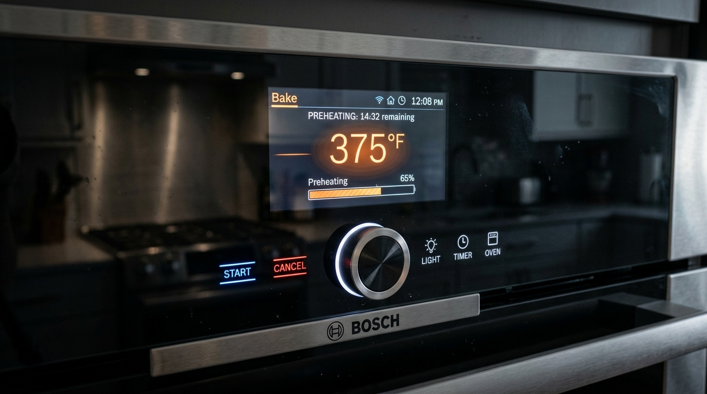
- Monitor the oven for 15 minutes. The cavity should begin heating, the preheat progress bar or temperature readout should climb steadily, and the F3 code should remain cleared.
Common Mistakes Homeowners Make
- Dropping the Wiring Harness Down the Back Wall: When unplugging the sensor from inside the oven, the wire harness can retract like a rubber band back through the insulation hole. If you let go of the plug before securing it, you will have to pull the heavy oven out and take the back panels off just to retrieve it.
- Purchasing Unverified Third-Party Sensors: Inexpensive knockoff sensors sold on open marketplaces often have poor manufacturing tolerances. Their resistance curve might deviate significantly from OEM parameters, causing your oven to cook 50°F hotter or colder than indicated.
- Using Standard Plastic Wire Nuts: Standard blue, orange, or yellow wire nuts are rated for residential junction boxes, not 500°F oven walls. They will liquefy during normal baking or a self-clean cycle.
- Skipping the Hard Reset: Always verify the fault code returns before tearing apart the oven. Control boards occasionally misinterpret line spikes as sensor dropouts.
Frequently Asked Questions
Can I still use my oven while the F3 code is showing?
No. The F3 code is a primary safety lockout. When the control board detects an open sensor, it instantly disables the bake, broil, and convection elements to prevent a runaway thermal event. You must clear the electrical fault before the oven will heat again. The cooktop surface burners, however, will usually continue to function normally on freestanding ranges.
Why did my oven sensor fail suddenly?
Oven sensors operate in an extreme thermal environment. Over years of thermal cycling—expanding during 450°F baking or 800°F self-clean cycles and contracting as the unit cools—the tiny platinum wire inside the probe fatigues. Eventually, thermal stress causes the microscopic wire to sever, instantly opening the circuit and triggering the F3 code.
Can I clean the oven temperature probe to fix an F3 error?
Cleaning will not fix an F3 code. Baked-on grease or carbon on the outside of the probe can cause temperature inaccuracy (such as your food burning or taking too long to bake), but it cannot break the internal electrical circuit. An F3 code is an electrical discontinuity inside the probe or wiring, which surface cleaning cannot resolve.
How do I find the correct replacement sensor for my GE oven?
Do not rely solely on the model number printed on the owner’s manual cover, as manuals cover broad product families. Locate the official model and serial tag on the actual appliance. On GE ranges, this sticker is typically on the frame behind the lower storage/warming drawer or around the interior door jamb. Use that exact model string when ordering your OEM sensor.
Is it safe to run a Self-Clean cycle after replacing the sensor?
Yes, provided you installed an OEM-grade sensor and secured all wiring correctly. However, we suggest testing the oven through several standard bake cycles at 350°F and 450°F first to ensure stable operation before subjecting the new component to the extreme thermal demands of a self-clean cycle.
Safety Precaution Notice
Before proceeding with any repair checklist: Always unplug the appliance from its electrical socket and turn off shutoff valves for incoming water (for washers and dishwashers). Discharge capacitors if working on motors.