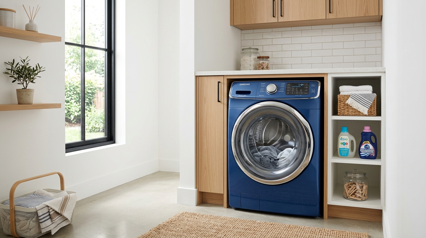
LG Washing Machine LE Error Code: Step-by-Step Fix
Required Tools for this Fix
- Socket wrench set
- Screwdriver
Quick Summary Answer: The LG washing machine LE error code indicates a “Locked Motor” (Locked Rotor) error, which happens when the drive motor cannot rotate the drum freely. The most common causes are an oversized laundry load, a faulty Hall sensor (rotor position sensor), or an electrical glitch triggering the thermal overload protector. You can often clear it by performing a hard reset: unplug the washer, hold the START/PAUSE button for 5 seconds, leave it unplugged for 20 minutes, and plug it back in.
What Does the LG LE Error Code Mean?
Modern LG front-load and top-load washers use an advanced Direct Drive system. Instead of using a traditional rubber belt and pulley assembly, LG mounts a brushless motor directly to the back of the wash tub.
+-------------------------------------------------------------+
|                  LG DIRECT DRIVE MOTOR HUB                  |
|                                                             |
|   [Main PCB] <---> [Wire Harness] <---> [Hall Sensor]       |
|                                                |            |
|                                         [Stator Coils]      |
|                                                |            |
|   [Wash Drum] <======================== [Rotor Hub]         |
+-------------------------------------------------------------+
When you see the LE code illuminate on your control panel, the washer’s main printed circuit board (PCB) has detected that the motor is drawing too much amperage or cannot achieve its commanded rotational speed. In simple terms, the control board thinks the motor is seized, mechanically jammed, or failing to communicate its position.
This error is designed to protect your motor windings and electronic inverter board from burning out under severe load.
LG Washer LE Error Diagnostic Overview
Use this reference table to evaluate the time, tools, and typical costs associated with diagnosing and repairing each potential failure point.
| Diagnostic Step | Est. Time | Tools Needed | Est. DIY Cost |
|---|---|---|---|
| System Hard Reset & Load Reduction | 20–25 Mins | None | $0 |
| Drum Obstruction Inspection | 10 Mins | Flashlight | $0 |
| Rotor Bolt & Hub Spline Inspection | 20 Mins | 17mm socket, ratchet, Phillips screwdriver | $0 |
| Rotor Position (Hall) Sensor Replacement | 30–45 Mins | 10mm & 17mm sockets, screwdriver | $15 – $35 |
| Stator Winding Resistance Test | 30 Mins | Digital multimeter, 10mm socket | $0 – $120 (if stator is bad) |
| Wiring Harness Continuity Check | 25 Mins | Multimeter | $0 – $30 |
| Main PCB / Inverter Board Diagnostic | 30 Mins | Phillips screwdriver, multimeter | $130 – $250 |
WARNING: HIGH VOLTAGE RISK
Always disconnect your washing machine from the electrical wall outlet before removing any access panels or touching internal components. LG Direct Drive stators and capacitors can store high electrical energy. Never run diagnostic continuity or resistance checks while the machine has live power connected.
Step-by-Step Diagnostic Testing Checklist
Work through this diagnostic checklist in sequential order, from simplest to most advanced.
[ ] Step 1: Power cycle and reset internal control logic
[ ] Step 2: Check for wash load binding, weight limits, and drum friction
[ ] Step 3: Inspect for tub seal/bellows foreign object pinches
[ ] Step 4: Remove rear panel and inspect the rotor mounting bolt
[ ] Step 5: Inspect rotor hub splines and magnets for physical damage
[ ] Step 6: Test stator coil resistance with a digital multimeter
[ ] Step 7: Test the Hall (Rotor Position) Sensor wiring and sensor body
[ ] Step 8: Inspect lower wiring harness for broken wires or pinched insulation
[ ] Step 9: Verify output voltage from the main inverter PCB
Phase 1: Zero-Tool Quick Fixes
Before disassembling your machine, rule out software communication errors, thermal safety trips, and load balance issues.
                  +-------------------------+
                  |   LE Code Appears       |
                  +-------------------------+
                               |
                               v
                  +-------------------------+
                  | Unplug & Hold START for |
                  | 5 Seconds (Drain Power) |
                  +-------------------------+
                               |
                               v
                  +-------------------------+
                  | Wait 20 Minutes (Allow  |
                  | Thermal Switch to Cool) |
                  +-------------------------+
                               |
            +------------------+------------------+
            |                                     |
            v                                     v
     [ Drum Spins Free ]                  [ Drum Still Locked ]
            |                                     |
            v                                     v
  Reduce Wash Load Weight;               Proceed to Phase 2:
  Run Spin-Only Test Cycle               Mechanical Disassembly
1. Perform a Microprocessor Hard Reset
LG washing machines monitor motor temperature via a software-driven thermal protection algorithm or an internal thermal fuse. A power surge, momentary stall, or heavy load can trigger a false-positive LE code.
- Press the POWER button to turn the unit off.
- Unplug the power cord directly from the wall outlet.
- While the washer is unplugged, press and hold the START/PAUSE button for 5 seconds to discharge residual power stored inside the circuit capacitors.
- Leave the machine unplugged for 20 to 30 minutes. This downtime allows the motor’s internal thermal protection switch to cool down and close its contacts.
- Plug the unit back in and power it on. Run a simple Rinse & Spin cycle with no clothes inside to verify operation.
2. Check for Drum Overloading
Washers have strict weight thresholds. If you pack king-size comforters, multiple heavy bath mats, or dense denim items together, the weight can exceed the initial startup torque limits of the direct-drive stator.
When the drum is overloaded, the motor tries to rock back and forth to distribute the clothes. If it cannot complete a quarter revolution within a predetermined number of milliseconds, it logs the LE code.
Take out half of the clothing load. Manually spin the empty drum using your hand. It should spin smoothly with little resistance.
Phase 2: Mechanical Inspection
If the reset fails and the drum feels stiff or catches when turned manually, a mechanical item is jamming the unit.
1. Clear the Door Bellows & Tub Gap
Small garments (baby socks, underwire bras, coins, nails, or washcloths) can slip past the rubber door gasket (boot) and get wedged between the rotating spin basket and the outer plastic tub.
       +--------------------------------------------+
       | FRONT VIEW OF INNER DRUM & DOOR GASKET     |
       |                                            |
       |             [ Outer Tub ]                  |
       |        +---------------------+             |
       |        |   [Rubber Gasket]   |             |
       |        |   +-------------+   |             |
       |        |   | (Look Here  |   |             |
       |        |   |  For Trapped|   |             |
       |        |   |  Objects!)  |   |             |
       |        |   |             |   |             |
       |        |   +-------------+   |             |
       |        +---------------------+             |
       +--------------------------------------------+
- Open the door and pull back the folds of the rubber door gasket.
- Shine a bright flashlight into the perimeter between the stainless steel drum and the rubber seal.
- Turn the drum slowly by hand through a full 360-degree rotation. Listen for scraping noises.
- If you spot an underwire or coin lodged in the drain holes or tub lip, extract it using needle-nose pliers.
2. Inspect Rear Rotor Hub Splines
The Direct Drive system relies on teeth (splines) connecting the metal motor rotor to the drum shaft. If these splines strip out, the motor slips and throws an LE code.
- Shut off the water supply valves, disconnect the fill hoses, and pull the washer away from the wall.
- Unplug the electrical power cable.
- Remove the four to six screws securing the rear metal access cover. Set the cover aside.
- In the center of the motor assembly, you will see a large metal disc (the rotor) secured by a 16mm or 17mm center bolt.
- Check if the center bolt is loose. If this bolt backs out even a fraction of an inch, the rotor disengages from the shaft splines.
Phase 3: Electrical & Component Diagnostics
If the mechanical systems are clear, the error is likely caused by the rotor position sensor, stator coils, or the interconnecting wire harness.
+------------------------------------------------------------------+
|                    REAR MOTOR ASSEMBLY DETAIL                    |
|                                                                  |
|   [ Rotor Cover ]  --->  [ 17mm Center Bolt ]                    |
|          |                                                       |
|          v                                                       |
|   [ Stator Ring ]  --->  [ Six 10mm Mounting Bolts ]             |
|          |                                                       |
|          v                                                       |
|   [ Hall Sensor ]  --->  [ Snapped onto Stator Frame at 7 o'clock] |
+------------------------------------------------------------------+
1. Remove the Rotor and Stator Assembly
To reach the electrical sensors, you must safely remove the motor components.
- Use a 17mm socket wrench to remove the center rotor bolt (turn counterclockwise). Have a helper hold the drum from the front, or hold the outer edge of the rotor disc steady to prevent it from turning.
- Grab the outer edges of the rotor disc with both hands. Pull straight back toward yourself. Watch your fingers: Strong permanent magnets line the inside rim of the rotor, which will pull back against the steel stator.
- Inspect the plastic teeth inside the center hub of the rotor. If the plastic splines are rounded, sheared off, or cracked, replace the rotor assembly.
- You will now see the stationary stator ring with its copper coils. Unplug the two wiring clip connectors at the bottom edge of the stator.
- Remove the six 10mm bolts securing the stator ring to the tub rear bearing housing.
- Gently pull the stator straight off the rear housing.
2. Test and Replace the Hall Sensor (Rotor Position Sensor)
The Hall sensor monitors the speed, direction, and magnetic position of the rotor. A broken Hall sensor is the single most common cause of the LG LE error code.
                  HALL SENSOR TEST CONFIGURATION

                 +-------------------------------+
                 |   [ 1 ]   [ 2 ]   [ 3 ]   [ 4]|
                 |    Vcc    GND      Ha      Hb |
                 +-------------------------------+
                               |       |       |
                 (+) Lead -----+       |       |
                 (-) Lead -------------+       |
                     [ Check Resistance: 8k - 12k Ohms ]
                 (-) Lead ---------------------+
                     [ Check Resistance: 8k - 12k Ohms ]
The sensor snaps directly onto the plastic frame of the stator assembly.
Visual Inspection
Inspect the sensor’s housing for cracks, burn marks, or moisture corrosion on the pin terminals. Corrosion causes signal degradation that tricks the main PCB into stopping the motor.
Resistance Testing
Set your digital multimeter to the kilo-ohms (kΩ) scale.
- Locate the sensor terminals: Pin 1 (Vcc / Power), Pin 2 (Ground), Pin 3 (Sensor Output A), Pin 4 (Sensor Output B).
- Place the positive multimeter test probe on Pin 1 (Power).
- Place the negative multimeter test probe on Pin 3 (Output A). You should see a reading between 8kΩ and 12kΩ (typically around 10kΩ).
- Move the negative probe to Pin 4 (Output B). You should measure the identical resistance range of 8kΩ to 12kΩ.
- Connect your probes across Pin 2 (Ground) and Pin 3, then Pin 2 and Pin 4. Readings should show infinite resistance (Open Loop / O.L.).
- If any reading shows an open circuit (0.00 or infinite resistance where 10kΩ is expected), the sensor is defective.
+-----------------------------------------------------------------+
| PRO TIP: Hall sensors can fail intermittently when hot.         |
| Because an OEM replacement Hall Sensor (Part # 6501KW2002A /    |
| 6501KW2001A) costs under $30, we suggest replacing it whenever  |
| you disassemble the stator on a machine older than 4 years.    |
+-----------------------------------------------------------------+
3. Test Stator Coil Winding Resistance
If the Hall sensor tests fine, the copper windings inside the stator ring may have developed a short or open circuit.
                   STATOR COIL TERMINAL BLOCK

                       +---------------+
                       | [1]  [2]  [3] |
                       |  U    V    W  |
                       +---------------+
                         |      |    |
           Test Pair A: [1]----+    |
           Test Pair B:        [2]---+
           Test Pair C: [1]----------+

           Target Value: ~5 to 15 Ohms across all pairs
- Set your digital multimeter to the lowest Resistance / Ohms (Ω) setting (e.g., 200Ω scale).
- Locate the 3-pin power connector on the stator frame. The terminals correspond to the motor phases: Phase U (Pin 1), Phase V (Pin 2), and Phase W (Pin 3).
- Measure resistance between Pin 1 and Pin 2. Note the value.
- Measure resistance between Pin 2 and Pin 3. Note the value.
- Measure resistance between Pin 1 and Pin 3. Note the value.
- Evaluate the readings: All three measurements must be balanced and fall between 5Ω and 15Ω (most LG stators read between 8Ω and 12Ω depending on the model).
- If any reading displays an open loop (O.L.), zero ohms (shorted), or varies by more than 1 ohm from the other phases, the stator has burnt out and needs to be replaced.
- Measure each pin to the metal frame of the stator. Your meter must read open loop (O.L.). If continuity exists to ground, the stator winding insulation is breached.
4. Check the Wiring Harness for Continuity & Damage
Vibration over years of high-speed spin cycles can rub the lower motor wiring harness raw against the metal chassis or the edge of the wash tub.
       +-------------------------------------------------------+
       | TYPICAL WIRING HARNESS PINCH / RUB POINT              |
       |                                                       |
       |  [Main PCB Top]                                       |
       |        \                                              |
       |         \  Wire Bundle Taped Along Cabinet Wall       |
       |          \                                            |
       |           * <-- [Look Here For Chafing / Broken Wire] |
       |          /                                            |
       |  [Direct Drive Motor Connections at Tub Bottom]       |
       +-------------------------------------------------------+
- Trace the wiring harness running from the Hall sensor and stator up to the main control board.
- Look for crushed wires, broken insulation, or melted conduits near the suspension springs and shock absorbers.
- Unplug the harness at the main PCB and at the motor.
- Set your meter to Continuity mode (Beep test).
- Test every wire end-to-end between the PCB connector and the motor sensor connector. If a wire does not beep, it has an internal snap. Splice the broken section with marine-grade heat-shrink connectors or replace the sub-harness.
Phase 4: Main Control Board & Inverter Drive Diagnostics
If the Hall sensor, stator, and wiring harness check out, the failure points to the power inverter circuitry on the main control board.
+------------------------------------------------------------------+
|               MAIN CONTROL PCB INVERTER STAGE                    |
|                                                                  |
|  [Incoming 120V AC] ---> [Rectifier Stage] ---> [Filter Caps]    |
|                                                      |           |
|                                                      v           |
|  [Stator Motor Output] <--- [IPM - Inverter Power Module]        |
|                             (Look for burn marks/cracked resin)  |
+------------------------------------------------------------------+
The main PCB converts standard 120V AC wall power into 3-phase variable-frequency DC power using an Intelligent Power Module (IPM). When this module blows:
- The board can no longer switch motor phases cleanly.
- The motor may twitch, hum, or shutter for 2 seconds, then display the LE code.
- The drum will not complete a smooth revolution under power.
How to Inspect the PCB:
- Unplug the washer from the wall.
- Remove the top panel of the washer (held by two rear screws; slide the panel backward and lift).
- Unclip the main control board assembly housing found along the top or side frame.
- Inspect the clear silicone waterproofing gel (potting compound) covering the board.
- If you see blackened resin, burn smells, or cracked capacitor casings near the motor output connector, the inverter module has failed. Replace the complete main control board assembly.
Complete Reassembly Procedure
Once you have identified and replaced the bad component, reassemble the direct drive assembly:
                  REASSEMBLY TORQUE & ALIGNMENT

   Step 1: Stator onto Tub Housing  ---> Hand-tighten 6 bolts evenly;
                                         Torque to ~8-10 ft-lbs.

   Step 2: Connect Hall Sensor Clip ---> Ensure locking tab clicks firmly.

   Step 3: Slide Rotor onto Shaft   ---> Keep hands flat on outside face.

   Step 4: Rotor Center Bolt        ---> Add medium blue threadlocker;
                                         Torque to 35-40 ft-lbs.
- Position the Hall sensor firmly onto the stator frame until both retaining tabs click into place.
- Mount the stator assembly onto the rear tub bearing housing. Thread all six 10mm mounting bolts by hand first to avoid cross-threading.
- Tighten the six stator bolts in a star pattern to approximately 8 to 10 ft-lbs of torque.
- Reattach the stator ground wire and both multipin wiring harness plugs. Ensure the plastic locking clips click securely.
- Slide the rotor disc carefully onto the splined center shaft. Magnets will grab the assembly as it gets close; keep your hands on the outer face of the rotor to avoid pinching your fingers.
- Clean the threads of the 17mm center bolt. Apply two drops of medium-strength (blue) threadlocker to the threads.
- Thread the center bolt in and torque it down to 35 to 40 ft-lbs. If you do not have a torque wrench, tighten it firmly with a standard ratchet until it bottoms out, then apply an additional 1/4 to 1/2 turn.
- Reinstall the rear metal access shield.
- Connect water hoses, plug in the main power cord, and run an empty test cycle.
Best Practices to Prevent Future LE Errors
To prevent the motor from locking or burning out replacement sensors in the future, apply these operational guidelines:
- Avoid Suds Lock from Excess Detergent: Using too much standard detergent or non-HE soap produces excessive foam. Suds create severe viscous drag between the outer tub and inner drum, stalling the motor and triggering an LE code. Use no more than 2 tablespoons of 2X High-Efficiency (HE) detergent per load.
- Balance Heavy Bulky Loads: When washing heavy items like bath rugs, dog beds, or pillows, always wash them in pairs to balance the load weight across the axis. Single heavy items clump to one side, preventing the direct-drive rotor from achieving balanced rotational inertia.
- Keep Wash Temperatures Varied: Running only cold-water cycles can allow soap scum and scale to build up behind the drum basket. This buildup increases rotational drag over time. Run an empty hot tub clean cycle once per month using an oxygenated washer cleaner.
Frequently Asked Questions (FAQ)
Can overloading my washer cause a permanent LE error?
Overloading usually triggers a temporary LE code by tripping the internal thermal overload safety switch. However, running severely heavy loads repeatedly can strip the plastic rotor hub splines or cause the stator copper windings to overheat, which permanently damages the motor and requires parts replacement.
What is the difference between the LG LE code and the OE code?
The LE code indicates a motor drive failure (Locked Motor Error), meaning the drum cannot rotate properly. The OE code indicates a drainage issue (Original Evacuation Error), meaning the washer cannot drain water out of the drum within the required time window due to a clogged drain pump filter or bad pump motor.
How do I know if my Hall sensor is bad without taking the machine apart?
If you initiate a cycle and you hear the control board relays click, followed by the drum slightly jerking or twitching back and forth without turning smoothly, the Hall sensor has likely lost one of its positioning phases. A dead Hall sensor usually prevents any smooth continuous rotation.
Is it worth fixing an LE error on an older LG washer?
Yes. The most frequent cause of an LE code is the Hall sensor, which costs around $15 to $35 and takes under an hour to install yourself. Even a replacement stator motor averages only $80 to $120. Compared to the cost of a new front-load washer ($750–$1,200), repairing the direct drive system is cost-effective.
Can a worn drum bearing cause the LE error code?
Yes. If the rear tub spider arm breaks or the stainless steel ball bearings corrode and seize, the drum will bind up mechanically. This severe mechanical resistance overworks the direct drive motor, causing an over-amperage state that trips the LE error code. If you spin the drum by hand and hear a loud roaring sound, check the bearings.
Safety Precaution Notice
Before proceeding with any repair checklist: Always unplug the appliance from its electrical socket and turn off shutoff valves for incoming water (for washers and dishwashers). Discharge capacitors if working on motors.